Sheet Metal Gauge Tables
If you’re working with sheet metal design in SolidWorks, understanding gauge tables is key to getting precise, reliable results. Sheet metal gauge tables are reference charts that define the thickness of sheet metal based on standard gauge numbers. These tables help you match your design parameters exactly to the physical materials you’ll use in fabrication.
What Are Sheet Metal Gauge Tables
Sheet metal gauge tables list thicknesses associated with different gauge numbers for various materials like steel, aluminum, and stainless steel. Each gauge corresponds to a specific thickness measurement, which can vary by metal type. These tables ensure you know exactly how thick your sheet metal is, making it easier to plan bends, cutouts, and other features accurately.
Types of Gauge Tables
There are several types of gauge tables, typically organized by material and regional standards, such as:
- Standard Gauge Tables: Commonly used for mild steel according to ASTM or US Sheet Metal Gauge standards.
- Material-Specific Tables: For aluminum, stainless steel, or galvanized steel with thickness variations.
- Custom Gauge Tables: Created to match specific shop or project requirements for unique materials or thicknesses.
Each type serves different needs but all focus on providing precise thickness info critical for your SolidWorks sheet metal designs.
Benefits of Using Gauge Tables in SolidWorks
Incorporating gauge tables in SolidWorks helps you:
- Ensure Design Accuracy: Your sheet metal parts will reflect real-world thicknesses, improving fit and function.
- Streamline Fabrication: Manufacturers can directly use your design specs, reducing back-and-forth questions.
- Enhance Bend Calculations: Gauge tables influence bend allowance and K-factors for more precise flat patterns.
- Maintain Consistency: Standardizing thicknesses across projects keeps production quality high.
Why Use Gauge Tables in SolidWorks
SolidWorks lets you import and link gauge tables directly into your sheet metal environment, making design setup much faster and less prone to errors. When you use gauge tables, you’re aligning your digital design with real-world manufacturing standards, which is essential for CNC sheet metal fabrication and precision machining.
By relying on these tables, you reduce costly trial and error, produce more reliable flat patterns, and ultimately save time during prototyping and production. If you want efficient SolidWorks sheet metal design that meets fabrication shop standards, integrating gauge tables is non-negotiable.
Step-by-Step Guide to Importing Gauge Tables in SolidWorks
Locating the Gauge Table Directory
Before you import, you need to know where SolidWorks keeps its sheet metal gauge tables. These files are usually stored in the SolidWorks installation folder under:
C:\ProgramData\SOLIDWORKS\SOLIDWORKS <version>\sheetmetal\gauge tables
This is where SolidWorks looks for gauge tables during sheet metal design.
Downloading or Creating Gauge Tables
If you don’t have the right gauge table, you can:
- Download standard gauge tables from trusted sources or manufacturer websites.
- Create your own custom gauge tables using Excel or a text editor. Make sure the format matches SolidWorks requirements (usually tab-delimited text files).
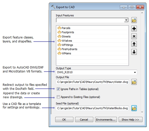
Importing Gauge Tables into SolidWorks
To bring gauge tables into SolidWorks:
- Copy your gauge table file into the gauge table directory mentioned above.
- Open SolidWorks and go to Tools > Options > System Options > Sheet Metal.
- Under the gauge table section, select your newly added table from the list.
- Apply the settings and close the dialog. Your gauge table is now ready to use in sheet metal parts.
Troubleshooting Import Issues
If your gauge table doesn’t show up or loads incorrectly:
- Double-check the file format and ensure it’s saved as a .txt file with correct delimiters.
- Verify the file is in the correct directory.
- Restart SolidWorks after copying the file to refresh the options.
- Make sure the gauge table data matches SolidWorks’ expected columns and units.
Following these steps will make sure you can easily import and use custom or standard sheet metal gauge tables in SolidWorks.
Using Gauge Tables in Sheet Metal Design
Creating a Sheet Metal Part
When starting a sheet metal design in SolidWorks, using gauge tables makes the process smoother. First, create a new sheet metal part by selecting the Sheet Metal tab and choosing your base face or sketch. Gauge tables automatically provide thickness values based on the material and gauge you select, so your part dimensions match real-world standards.
Configuring Sheet Metal Parameters
After setting up the initial part, configure the sheet metal parameters. This includes thickness, bend radius, bend allowance, and K-factor. With gauge tables imported, you’ll find preset thickness options reflecting common gauge sizes. Simply pick the gauge from the table, and SolidWorks will adjust the other values accordingly—saving time and reducing errors in manual input.
Verifying Design Accuracy
Once your part is modeled with the correct gauge thickness, verify the design’s accuracy by reviewing the flat pattern view. Make sure the bend allowances and radii match expected standards. Using gauge tables helps ensure dimensions and bend calculations align with manufacturing needs and CNC sheet metal fabrication processes. This reduces the risk of costly mistakes during production.
For more on optimizing your sheet metal designs, check out our guide on using design for manufacturing and assembly for easier sheet metal fabrication.
Best Practices for Sheet Metal Gauge Tables

Aligning with Fabrication Shop Standards
Make sure your gauge tables match the standards used by your local fabrication shop. This keeps your SolidWorks sheet metal design accurate when it hits the shop floor. Using the right gauge and thickness values means your parts will fit correctly and bend as expected during CNC sheet metal fabrication.
Maintaining and Updating Gauge Tables
Keep your gauge tables up to date. Material specs and machine capabilities can change, so review your tables regularly. Update thickness values, bend radius data, and K-factors to reflect real-world conditions. This saves time and avoids costly errors in production.
Avoiding Common Mistakes
- Don’t mix gauges and thicknesses from different standards or sources.
- Avoid outdated or generic tables—customize gauge tables based on your materials and machines.
- Double-check imported gauge tables for errors before use in your SolidWorks flat pattern.
- Confirm that bend allowances and radii align with your CNC machining shop’s tools and capabilities.
Following these best practices ensures your sheet metal design in SolidWorks runs smoothly from modeling to fabrication.
How HYCNC Enhances Your SolidWorks Workflow
HYCNC’s Gauge Tables and CNC Expertise
HYCNC offers expertly crafted sheet metal gauge tables designed to integrate seamlessly with your SolidWorks sheet metal design process. These tables are built with real-world CNC sheet metal fabrication in mind, ensuring that your bend allowances, K-factors, and flat patterns line up perfectly with actual shop capabilities. By using HYCNC’s gauge tables, you reduce guesswork and improve precision, helping you create designs that are ready to manufacture without costly errors.
Additional Tools and Resources
Beyond gauge tables, HYCNC provides a range of CNC services including metal bending, metal etching, and sheet metal fabrication that complement your SolidWorks projects. Their in-depth guides and tutorials help you master design for manufacturing concepts, making it easier to optimize your sheet metal parts for both function and fabrication. You’ll find resources tailored to improve your workflow, saving you time and aligning your CAD models with real CNC machining processes.
Why Choose HYCNC for Sheet Metal Fabrication
Choosing HYCNC means partnering with experienced professionals who understand both the software and the shop floor. Their combination of CNC expertise and detailed SolidWorks gauge tables ensures your designs translate smoothly into precision parts. Whether you’re working on simple brackets or complex enclosures, HYCNC helps you maintain accuracy and efficiency from design to final product. For more insights on sheet metal fabrication and design tips, check out their sheet metal bracket guide and design for manufacturing resources.
FAQs
Difference Between Gauge Tables and Bend Tables
Gauge tables and bend tables serve different roles in SolidWorks sheet metal design. Gauge tables list material thicknesses along with their corresponding sheet metal gauges, helping to set up accurate flat patterns. Bend tables, on the other hand, define bend allowances and K-factors for specific bend angles and materials, ensuring precise bend geometry. Both are essential but focus on different stages of sheet metal modeling.
Using HYCNC’s Gauge Tables with Other CAD Software
HYCNC’s gauge tables are designed primarily for SolidWorks, but they can often be adapted for use with other CAD platforms that support custom thickness and gauge standards. Always check file format compatibility and make necessary adjustments for bend allowance values to maintain accuracy across different CAD environments.
Troubleshooting Gauge Table Import Issues
If you hit snags importing gauge tables into SolidWorks, consider the following:
- Confirm the gauge table file format matches SolidWorks requirements (usually .xls or .xlsx).
- Verify the file path is correctly linked within SolidWorks sheet metal settings.
- Check for corrupt or improperly formatted table data.
- Restart SolidWorks after importing changes.
- Update SolidWorks to the latest version if persistent errors occur.
Supported Materials by HYCNC’s Gauge Tables
HYCNC’s gauge tables cover a range of common sheet metal materials used in CNC sheet metal fabrication, including:
- Mild steel
- Stainless steel
- Aluminum alloys
- Galvanized steel
This ensures your SolidWorks flat patterns and bend allowances align closely with real-world fabrication standards.
Ensuring SolidWorks Designs Are CNC Ready
To make sure your sheet metal designs in SolidWorks are ready for CNC machining, use accurate gauge tables to set thickness and bend allowances. Double-check your flat patterns for correct bend radii and K-factors. Submitting designs with aligned gauge tables and clean flat patterns helps avoid fabrication delays, ensuring seamless CNC processing at HYCNC or any fabrication shop.