Understanding the Convert to Sheet Metal Tool
What Is the Convert to Sheet Metal Tool
The Convert to Sheet Metal tool in SOLIDWORKS is designed to transform solid or surface bodies into sheet metal parts. Instead of building sheet metal features from scratch, this tool lets you take existing 3D models—even those not originally intended as sheet metal—and convert them into flat patterns that are ready for fabrication. This makes it easier to work with complex shapes and imported designs without having to remodel everything.
Using this tool offers several key benefits:
- Material efficiency by optimizing sheet usage
- Improved manufacturability thanks to accurate bend allowances and K-factors
- Better compatibility with CNC sheet metal fabrication processes like laser cutting and bending
When to Use Convert to Sheet Metal
The Convert to Sheet Metal tool is especially useful in situations like:
- Handling complex geometries that would be tough to model using traditional sheet metal features
- Working with imported models (like STEP or IGES files) that lack sheet metal data
- Converting solid parts or non-sheet metal designs to prepare them for CNC sheet metal fabrication
Compared to other SOLIDWORKS sheet metal tools—like Base Flange or Edge Flange—Convert to Sheet Metal shines when you need a fast, efficient way to flatten already existing models rather than building from scratch. It complements the standard sheet metal workflow by offering more flexibility with less upfront modeling effort.
Step-by-Step Guide to Using the Convert to Sheet Metal Tool
Step 1 Prepare Your Solid Model
Before you start, make sure your model is a solid or surface body with consistent thickness. This is key for smooth sheet metal conversion. When modeling complex shapes:
- Keep wall thickness uniform
- Avoid sharp internal corners
- Close all open surfaces
Step 2 Access the Tool
You can find the Convert to Sheet Metal tool in the Sheet Metal toolbar. If it’s not visible, go to Insert > Sheet Metal > Convert to Sheet Metal.
Step 3 Set Sheet Metal Parameters
Set a fixed face — this is the base face that stays flat during bending. Define the sheet thickness manually or use a gauge table if you have one set up. Customize bend radius, K-factor, and bend allowances to match your material specs and manufacturing process.
Step 4 Select Bend and Rip Edges
- Pick the edges where bends occur; these mark the folds in your sheet metal part.
- Use the Collect All Bends feature to automatically detect bend edges.
- Specify rip edges where gaps or cuts are needed between flanges for proper unfolding.
Step 5 Verify and Flatten
Check the FeatureManager for any errors after defining bends and rips. Use the Flatten tool to create the flat pattern and ensure the shape unfolds correctly without issues.
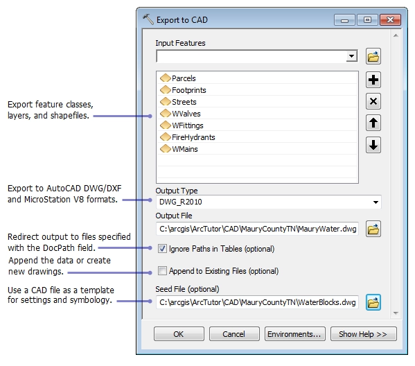
Step 6 Export for CNC Fabrication
Save the flat pattern as DXF or DWG files for laser cutting or STEP files for 3D CNC machining. If you’re working with HYCNC, follow their pre-flight checklist to verify holes and cutouts match the material thickness and processing requirements.
This step-by-step process helps you get your complex or imported models ready for precise CNC sheet metal fabrication while maintaining material efficiency and accuracy.
Best Practices for Optimal Results

Design Tips
To get the most out of the Convert to Sheet Metal tool in SOLIDWORKS, keep your design simple and consistent:
- Use consistent wall thickness — This helps avoid errors during conversion and flattening. Inconsistent thickness can cause issues with bend calculations and flattening accuracy.
- Test flattening often — Don’t wait until the end. Flatten your model early to catch geometry problems that can cause failures or misfits later.
Troubleshooting Common Issues
Sheet metal conversion isn’t always smooth, especially with complex shapes. Here’s how to stay on track:
- Handle non-cylindrical bends carefully — The tool may struggle with irregular bend shapes. Edit the Convert-Solid feature to tweak bend lines or add rip edges as needed.
- Iterate your design — Don’t hesitate to adjust your model step-by-step. The Convert to Sheet Metal feature supports this kind of iterative tweaking to refine bends and folds.
Integration with CNC Processes
At HYCNC, using accurate flat patterns from SOLIDWORKS is key for flawless CNC fabrication:
- Flat patterns ensure precise laser cutting and bending — We rely on your SOLIDWORKS sheet metal flat patterns to program our CNC machines with minimal guesswork.
- Accurate K-factors and bend deductions matter — These influence how the material behaves during bending. HYCNC uses the correct values to maintain part accuracy, reduce waste, and speed up production.
Following these best practices not only makes your design cleaner but also smooths the path from SOLIDWORKS modeling to CNC sheet metal fabrication. For more on designing for easier sheet metal workflows, check out our design for manufacturing and assembly tips.
Benefits of Using Convert to Sheet Metal for CNC Fabrication
Using the Convert to Sheet Metal tool in SOLIDWORKS offers several clear advantages when preparing parts for CNC fabrication.
Material Efficiency
It helps reduce waste by optimizing how sheet metal is laid out. The tool creates accurate flat patterns that make the best use of your sheet material, cutting down on scrap and saving you money.
Time Savings
By converting complex solid models directly into sheet metal parts, you skip the need to redesign from scratch. This streamlines the entire design-to-manufacturing workflow, letting you move faster from concept to production.
Precision
The tool ensures your flat patterns are accurate, which is key for precise CNC machining like laser cutting and bending. It accounts for bend allowances and K-factors, so the final parts match your design exactly.
Versatility
Convert to Sheet Metal works well with imported models and complex assemblies, giving you flexibility no matter where your design starts. This means less hassle when working with varied sources or legacy parts during CNC sheet metal fabrication.
How HYCNC Enhances Your Sheet Metal Projects
At HYCNC, we specialize in turning your SOLIDWORKS sheet metal designs into precision parts through advanced CNC processing services. Our capabilities include laser cutting, metal bending, and rapid prototyping, making us a one-stop solution for all your sheet metal fabrication needs.
We work directly with your SOLIDWORKS files, ensuring seamless collaboration and minimizing errors throughout the production process. Whether you’re working with complex converted sheet metal parts or custom flat patterns, our team ensures every detail meets your specifications for high-quality CNC sheet metal fabrication.
Ready to bring your design to life? Upload your SOLIDWORKS model to HYCNC today for a quick quote and start streamlining your sheet metal project from design to finished product.
FAQs
What types of models can be converted to sheet metal in SOLIDWORKS
You can convert most solid bodies with uniform thickness into sheet metal parts using the Convert to Sheet Metal tool. This includes parts you’ve designed from scratch or imported models that aren’t originally sheet metal. Models with consistent wall thickness and simple bend edges work best for smooth conversion.
How to fix errors when flattening a sheet metal part
If you get errors flattening your sheet metal, try these tips:
- Check for inconsistent or varying thicknesses in your model
- Make sure bends are cylindrical, not complex shapes
- Adjust bend radius and K-factors in the sheet metal parameters
- Edit the Convert to Sheet Metal feature to tweak bend or rip edges until it flattens without errors
Can Convert to Sheet Metal tool be used with imported files
Yes, the tool works well with imported CAD files like STEP or IGES. Just ensure the model has consistent thickness and clean geometry. This is handy for turning non-sheet metal parts from other software into flat patterns you can use for CNC sheet metal fabrication.
How HYCNC ensures precision in CNC sheet metal fabrication
At HYCNC, we rely on accurate SOLIDWORKS flat patterns generated with proper K-factors and bend allowances. Our CNC machines use DXF and STEP files directly from your design to ensure precise laser cutting and bending. We double-check hole sizes, material thickness, and bend parameters before fabrication to deliver tight tolerances every time.
Best file formats for CNC processing with HYCNC
For laser cutting and CNC bending, submit your designs as:
- DXF or DWG for 2D flat patterns
- STEP or Parasolid for 3D models and assemblies
These formats keep your sheet metal data intact and compatible with HYCNC’s CNC workflow, ensuring fast, accurate production.