L Brackets and Their CNC Applications
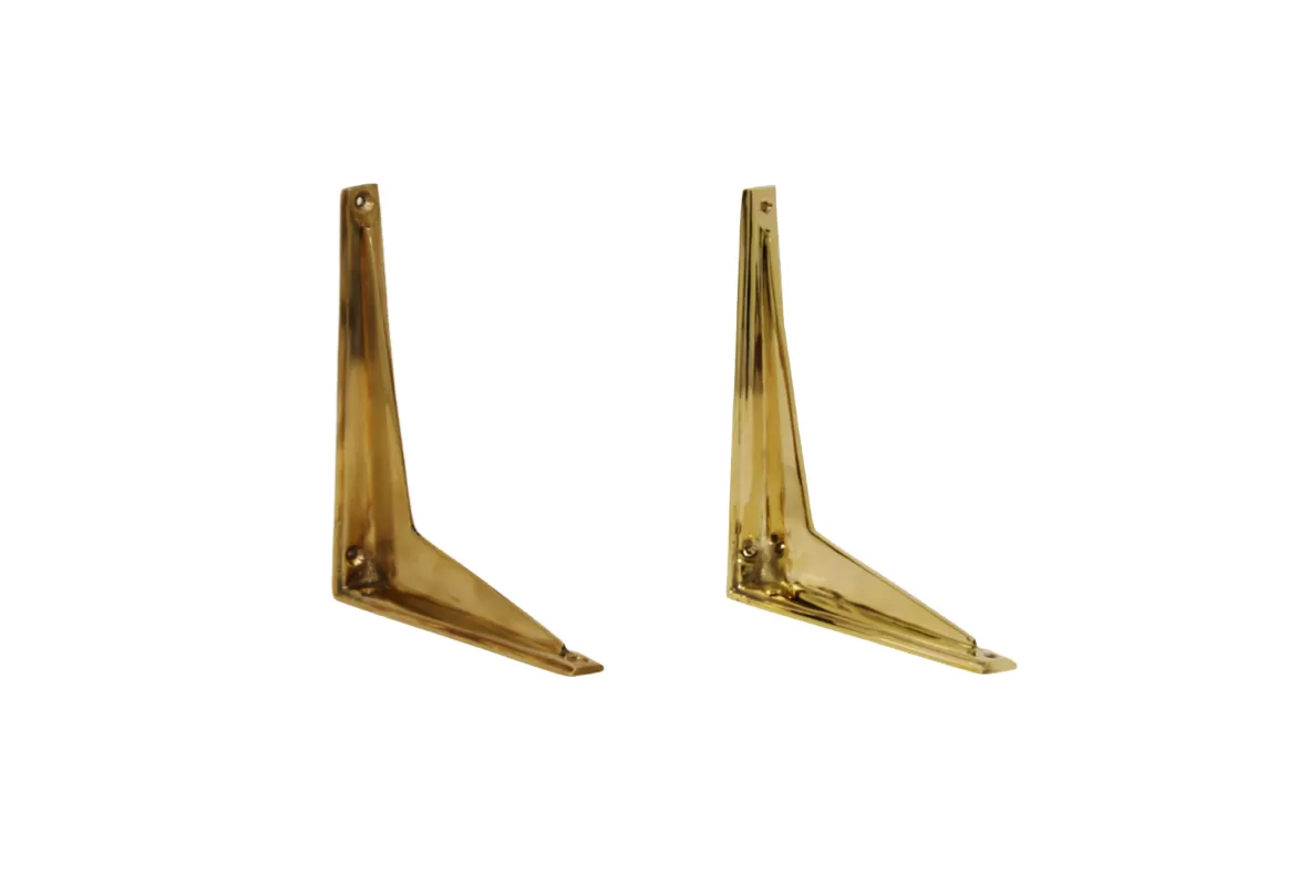
What is an L Bracket
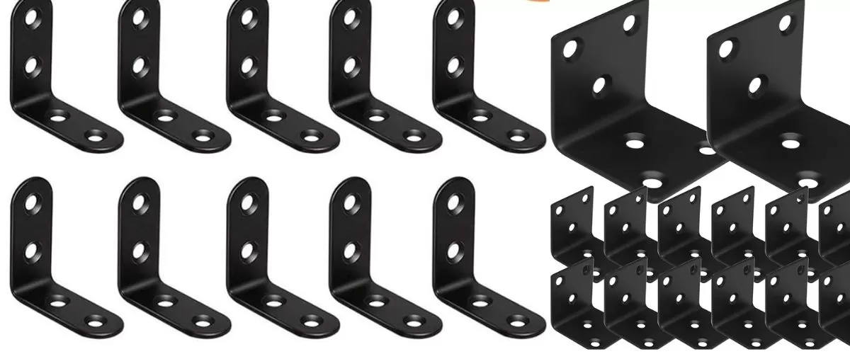
L brackets are simple, versatile metal or plastic parts shaped like the letter “L.” They are commonly used to join two surfaces at a right angle, providing structural support and stability in various applications. Whether in furniture assembly, shelving, or machinery, L brackets help secure components firmly while handling different load conditions.
Why Use Rhino3D
Rhino3D is a powerful CAD tool favored for its precision and flexibility in 3D modeling, making it ideal for designing L brackets. Unlike basic design programs, Rhino3D allows you to create detailed, accurate geometries with ease. You can model complex bends, apply neutral axis offsets for bending calculations, and unroll surfaces to prepare 2D profiles—critical steps for CNC machining preparation.
CNC Machining Considerations
When preparing L bracket designs for CNC machining, keep these key points in mind:
- Material Thickness and Bend Radius: Rhino3D lets you calculate and adjust the neutral axis offset to match the material thickness, ensuring bends form correctly without cracking.
- Flat Pattern Creation: Unrolling the 3D model into a precise 2D layout is essential for CNC laser cutting or milling.
- File Export: Preparing files in compatible formats like DXF guarantees smooth integration with CNC machines.
- Tolerance and Finish: CNC parts need attention to detail with tolerances and surface finishes to fit perfectly in assemblies.
Using Rhino3D for L bracket design simplifies these steps, giving you confidence that your files are ready for a smooth CNC machining process.
Step-by-Step Guide to Preparing an L Bracket in Rhino3D
Step 1 Set Up Your Rhino3D Workspace
Start by customizing your Rhino3D interface for efficient 3D modeling. Set units to inches or millimeters, depending on your project needs. Organize your layers for different parts such as the base, flanges, and bend lines. This cleanup helps avoid confusion down the line.
Step 2 Model the L Bracket Geometry
Using Rhino3D, create the basic shape of your L bracket with exact dimensions. Use commands like Box, Extrude, or Polyline to sketch the base and vertical flanges. Ensure the thickness matches your material specs.
Step 3 Offset the Neutral Axis for Bending
To prepare for accurate bending, offset the neutral axis inside the thickness of the material. Rhino3D bending calculators or formulas can help you shift this axis, accounting for material stretch and compression during bending. This step is crucial for precise CNC results.
Step 4 Unroll the Surface for 2D Linework
Unroll or flatten the 3D model’s bent surfaces to generate a 2D sheet layout. Rhino3D’s UnrollSrf command lets you convert the curved bends into flat lines, which is key for laser cutting or CNC punching.
Step 5 Create Bend Lines and Final Linework
Mark bend lines clearly on your 2D sheet. Use Polyline or Curve tools to indicate where the metal will fold. Differentiate these lines visually (e.g., dashed for bends, solid for cuts) so CNC operators know exactly where to process.
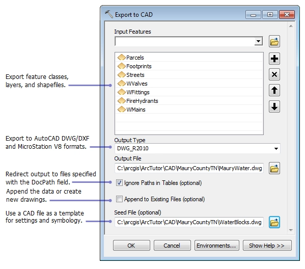
Step 6 Export the File for CNC Machining
Export your finalized 2D linework as a DXF or DWG file, formats widely accepted by CNC machines. Double-check layers and line styles before export to ensure your file is clean and easy to read.
Step 7 Pre-Flight Checklist
Before sending your file to CNC machining, review these:
- Dimensions and tolerances match your design
- Bend allowance and neutral axis offsets are accurate
- No open curves or naked edges in the file
- Correct file format and naming conventions
- All layers properly labeled
Following these steps will ensure your L bracket design in Rhino3D goes smoothly through CNC machining and fabrication. For additional tips on sheet metal brackets, check out our sheet metal bracket guide.
Best Practices for Optimizing L Bracket Designs
When designing an L bracket for CNC machining, a few key factors will help you get the best results and avoid costly mistakes.
Material Selection
- Choose materials that match your bracket’s intended use—common choices include aluminum for lightweight strength, stainless steel for corrosion resistance, and mild steel for heavy-duty support.
- Keep in mind how the material bends and its minimum bend radius to avoid cracks or deformation during forming.
- Thicker materials offer more strength but may require adjustments in your Rhino3D bending calculator for accurate neutral axis offsets.
Tolerances and Precision
- Always account for CNC machining tolerances—typical metal cutting machines have tolerance ranges around ±0.005 inches.
- Design your L bracket with a slight clearance if it needs to fit with other parts, ensuring smooth assembly.
- Use Rhino3D’s precise modeling tools to double-check dimensions before exporting your DXF file for CNC cutting or laser cutting L bracket operations.
Additional Features
- Consider adding relief cuts or bend reliefs to help prevent warping during bending.
- Include clear bend lines and notes when you prepare your Rhino3D CAD file prep to guide fabrication.
- If your design involves welding, leave enough space for weld seams without compromising strength.
Following these best practices ensures your L bracket design is ready for smooth CNC machining and reliable performance once fabricated.
Why Choose HYCNC for Your L Bracket Fabrication
When it comes to fabricating L brackets, HYCNC stands out for reliable precision and quick service tailored to your needs. Here’s why partnering with HYCNC makes sense:
Seamless File Integration
HYCNC accepts Rhino3D CAD file prep in all standard formats, including DXF and 3DM. This means your L bracket design transfers smoothly with no hassles or data loss, ensuring what you modeled is exactly what gets made.
Advanced CNC Capabilities
With state-of-the-art CNC machining, HYCNC handles complex geometries and tight tolerances required for high-quality L brackets. Whether you need laser cutting, bending, or milling, their equipment delivers consistent, precise parts every time.
Fast Turnaround
U.S.-based customers benefit from HYCNC’s efficient workflow and local production that shaves days off typical lead times. Quick delivery means your project keeps moving without waiting for overseas shipments or slow processing.
Ready to get your L bracket fabricated right the first time? Contact HYCNC today to discuss your Rhino3D model and get a custom quote. Their team is ready to help you turn digital designs into precision parts fast and hassle-free.
For more on designing sheet metal brackets like L brackets, check out our sheet metal bracket guide.
Troubleshooting Common Rhino3D Issues

When preparing an L bracket in Rhino3D, you might run into a few common problems. Here’s how to fix them quickly:
Fixing Naked Edges
Naked edges happen when your model surfaces don’t join properly, leaving gaps that cause errors in CNC machining. To fix this:
- Use the ShowEdges command and select “Naked Edges” to highlight gaps.
- Use Join to connect edges if they’re close.
- For stubborn edges, try MatchSrf to align surfaces or rebuild the surface using Rebuild.
Bad Objects
Sometimes a model cannot be processed because of bad geometry or corrupted data. Here’s what to do:
- Run Check to see if there are bad objects in your file.
- Use SelBadObjects to select and inspect them.
- Try RebuildEdges or MergeAllFaces to repair geometry. If the object is beyond repair, consider remaking the part.
File Export Errors
Exporting your L bracket model to CNC-friendly formats like DXF can cause errors if the file isn’t clean. Avoid this by:
- Making sure all surfaces are joined or baked into a solid.
- Checking that curves are closed and planar before export.
- Using the Export Selected option to isolate the final geometry.
- Verifying the export units match your CNC machine’s settings.
If you want more detailed help on preparing your sheet metal brackets in Rhino3D, check out this sheet metal bracket tutorial. It covers tips that apply to L bracket design too.
With these quick fixes, you’ll avoid delays and get your L bracket file ready for smooth CNC machining.
FAQs
What is the best way to prepare an L bracket file in Rhino3D for CNC?
Start by modeling the L bracket in 3D, offsetting the neutral axis for bending, and then unroll the surface to create 2D linework. Export the final file as a DXF for CNC machining. Following these steps ensures an accurate and machine-ready file.
Can I use Rhino3D for laser cutting L brackets?
Yes, Rhino3D is excellent for preparing laser cutting files. After modeling the bracket, use the unroll command and create precise bend lines to get your 2D layout. Export as a DXF file compatible with laser cutting machines.
How do I offset the neutral axis in Rhino3D for bending calculations?
Use Rhino’s offset tools with bending calculator plugins or manual calculations. Accurately offsetting the neutral axis helps prevent material stress and deformation during bending, ensuring your bracket fits perfectly after fabrication.
What file formats are best for CNC machining of L brackets?
DXF and DWG files are the standard for CNC laser cutting and punching. Rhino3D allows straightforward export of these formats, which your machining vendor will need.
How do I fix naked edges in Rhino3D models before CNC export?
Use the ShowEdges command to identify naked edges, then join surfaces or rebuild them to close gaps. Fixing these ensures your model is watertight and ready for CNC processing.
Where can I find more tips on designing sheet metal brackets in Rhino3D?
Check out our detailed guide on sheet metal bracket design and CNC preparation here: Sheet Metal Bracket Design and CNC Preparation for more insights.
Feel free to reach out to us at HYCNC if you need help with Rhino3D CAD file prep or L bracket fabrication—we’re here to make your CNC process smooth and reliable.