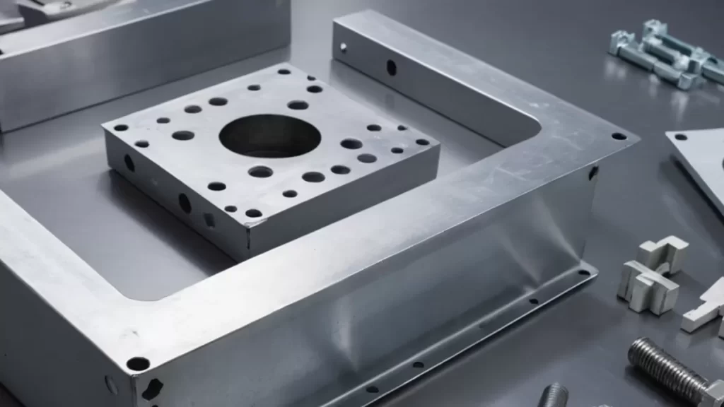
What Are Machining Tolerances
Machining tolerances refer to the allowable limits of variation in a manufactured part’s dimensions. In simple terms, they define how much a part’s size or geometry can deviate from the exact design specifications without affecting its function. Tolerances are essential because no machining process can produce parts with perfect accuracy every time.
There are several types of tolerances commonly used in CNC machining:
- Dimensional Tolerances: Control the size of features like length, diameter, or thickness.
- Geometric Tolerances: Control shape, orientation, and position of features beyond simple measurements.
- Surface Finish Tolerances: Specify the texture quality on a part’s surface.
Understanding and applying proper tolerances is crucial. They ensure parts fit together correctly, perform as intended, and minimize production costs by avoiding unnecessary precision.
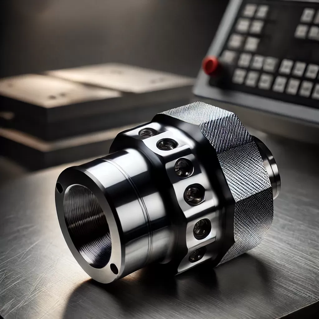
For example, a shaft designed with a diameter tolerance of ±0.01 inches means the manufactured shaft can be slightly larger or smaller than the nominal size but still work properly in its assembly. This balance keeps production efficient while maintaining product quality.
The Basics of Geometric Dimensioning and Tolerancing GD&T
Geometric Dimensioning and Tolerancing, or GD&T, is a system used in engineering and manufacturing to clearly define the size, shape, and allowable variation of parts. Unlike basic tolerancing that only sets limits on dimensions, GD&T controls the geometric relationships of features on a part, ensuring better clarity and precision.
The core elements of GD&T can be summed up with the acronym SLOF:
- Size – The physical dimensions of a feature like length, diameter, or width.
- Location – Where a feature is positioned relative to others on the part.
- Orientation – The angle or alignment of a feature in relation to a reference.
- Form – The shape characteristics such as flatness, straightness, and roundness.
Key components in GD&T include:
- Datum Reference Frame – This is the 3D coordinate system that serves as the starting point for measurements, based on key datums (reference surfaces).
- Feature Control Frame – A rectangular box containing the GD&T symbols, tolerance values, and datum references that define geometric requirements for features.
- Common Symbols – These include controls for flatness, perpendicularity, position, concentricity, and more, helping specify exactly how much variation is allowed.
GD&T has a long history, evolving from basic engineering drawings to a globally accepted language for precision manufacturing. It started gaining traction in the mid-20th century as industries needed more consistent, unambiguous ways to communicate part requirements, especially useful in CNC machining where high accuracy is a must.
Understanding GD&T means being able to ensure parts fit and function exactly as designed, which is why it’s critical for anyone working with machining tolerances and CNC manufacturing.
Why Machining Tolerances and GD&T Matter in CNC Manufacturing
Machining tolerances and GD&T play a crucial role in ensuring parts meet exact requirements in CNC manufacturing. Precision is key—whether it’s fitting engine components or creating aerospace parts—small deviations can cause big issues. For example, a shaft that’s even slightly off can lead to poor functionality or failure. GD&T helps define these limits clearly, so machinists know exactly how much variation is acceptable without sacrificing performance.
From a cost perspective, using proper tolerances avoids over-machining. Tight tolerances demand more time and higher precision tools, which can quickly drive up costs. By applying the right tolerance standards and GD&T rules, manufacturers balance accuracy with affordability, avoiding unnecessary expenses.
In mass production, interchangeability is essential. Parts made in different batches or even different factories must fit and function the same. That’s where clear machining tolerances and GD&T really shine, maintaining consistency and enabling smooth assembly lines.
Quality control also benefits significantly. Tolerance definitions and GD&T provide clear criteria for inspections, making it easy to spot defects early. This reduces scrap rates and rework, helping keep projects on schedule and within budget.
At HYCNC, we prioritize tight yet efficient tolerance management to meet our customers’ needs. We work closely with clients to determine the right tolerances for their parts, balancing precision, cost, and manufacturability. This approach ensures that every CNC machined component delivers reliable performance without wasting resources. For more on our precision capabilities, check out our precision machining services.
Key Standards for Tolerances and GD&T

When working with machining tolerances and GD&T, it’s crucial to follow recognized standards to ensure everyone is on the same page. The two main sets of standards used in the U.S. and worldwide are ISO and ASME.
ISO Standards
-
ISO 2768: This is one of the most common standards for general tolerances in machining. It sets guidelines for linear dimensions, angular dimensions, and geometric tolerances on parts without specific tolerance data. It’s especially useful for parts that don’t require tight precision but still need to meet quality checks.
-
ISO 286: This standard focuses on fits and tolerances for mating parts, like shafts and holes. It helps define how tightly or loosely parts should fit together, which is key in ensuring parts move as expected or stay securely fixed.
ASME Standards
- ASME Y14.5: This is the go-to standard for GD&T in the U.S. It provides detailed rules and symbols for defining and communicating geometric dimensioning and tolerancing on engineering drawings. ASME Y14.5 covers everything from datum reference frames to feature control frames, making it essential for precise CNC machining.
Comparing ISO and ASME Standards
- Scope: ISO tends to cover a broader range of general tolerances and systematizes fits internationally, while ASME Y14.5 dives deep into geometric tolerancing details.
- Usage: U.S. manufacturers and engineers usually rely on ASME for GD&T because it’s tailored to SAE and ANSI practices. ISO is more common in Europe and Asia but is also widely accepted in international projects.
- Symbols and Terminology: Both standards use similar symbols, but there are subtle differences in rules and interpretations, so consistency in the chosen standard is key.
In the CNC machining world, knowing which standard your project requires helps avoid costly mistakes and keeps production smooth. At HYCNC, we work closely with customers to ensure all parts meet the correct standards for the best fit, function, and finish.
Practical Applications of Tolerances and GD&T

Using machining tolerances and GD&T effectively is key in every phase of a CNC project, from design to inspection.
Design Phase Using GD&T
During the design stage, engineers use GD&T to clearly specify the allowable variations in part features. This helps avoid misunderstandings between design and production teams by providing a common language that defines size, form, orientation, and location. It ensures the part meets functional requirements without unnecessary tight tolerances that can increase cost and complexity.
Manufacturing Phase for Machinists
For machinists on the shop floor, clear tolerance specifications and GD&T symbols guide precise machining operations. It helps in selecting the right tools, machines, and processes to achieve the required accuracy. Understanding GD&T also allows machinists to focus on critical features rather than over-focusing on every dimension, saving time and resources.
Inspection Phase and Tools
In inspection, GD&T is essential for setting up measurement protocols. Tools like coordinate measuring machines (CMM), gauges, and calipers rely on the defined tolerance zones to verify if parts fall within acceptable limits. Using GD&T increases the accuracy of quality control and reduces guesswork during inspections.
Case Study Example from HYCNC
At HYCNC, we apply tight machining tolerances and GD&T best practices to support complex aerospace parts production. By integrating GD&T early in design and aligning it with CNC machining capabilities, we provide parts that meet rigorous standards with minimal rework. Our organized inspection routines based on feature control frames ensure consistent quality, proving the real value of precision tolerance management.
For more details on how CNC machining fits into precise manufacturing, check out our CNC machining services page.
Tips for Optimizing Tolerances in CNC Machining

Getting tolerances right in CNC machining is all about balance. Here are some straightforward tips to help you optimize tolerances for better results:
Avoid Over-Tolerancing
- Don’t set tighter tolerances than necessary. Over-tolerancing drives up costs and increases machining time without adding real value.
- Ask yourself if the part’s function really needs such tight control. If not, loosen the tolerance to save money and speed up production.
Consider Material Properties
- Different materials react differently during machining. Some expand, shrink, or deform more than others.
- Account for material behavior when setting tolerances to avoid parts that don’t fit or function as expected.
Align Process Selection with Tolerance Needs
- Match machining processes with the tolerance level you need. For example, processes like grinding or EDM offer finer tolerances than standard milling.
- Choosing the right method upfront saves rework and keeps your project on track.
Work Closely with HYCNC for Optimization
- At HYCNC, we collaborate with you to balance design intent and manufacturing capabilities.
- We help fine-tune tolerances for cost-effective, precise machining that fits your production goals.
- Leveraging our expertise early leads to better parts, fewer delays, and optimized budgets.
Following these tips ensures your CNC machining tolerances are smart, not strict. It helps you get reliable, high-quality parts without breaking the bank.
Common Challenges and Solutions
In CNC machining, one big challenge is misinterpreting GD&T symbols. These symbols control things like size, form, and position, and if read wrong, the whole part can fail inspection or not fit properly. To fix this, we suggest clear training and using standard references during design and manufacturing to keep everyone on the same page.
Another issue is cost problems caused by improper tolerances. Overly tight tolerances increase machining time and scrap rates, driving up expenses. On the flip side, loose tolerances might cause part failures down the line. Finding the balance is key.
At HYCNC, we offer expert support and consultation to help clients navigate these challenges. We assist in setting realistic tolerance goals and interpreting GD&T correctly, reducing errors and unnecessary costs. Our goal is to improve quality and keep projects efficient, which saves you time and money in the U.S. manufacturing market.