Understanding Kerf in CNC Cutting
Kerf is the width of material removed by a cutting tool during processes like laser, plasma, or waterjet cutting. Think of it as the gap the tool creates as it slices through your material. This small but important cut width affects the final dimensions of your part.
In many projects, especially those requiring tight tolerances, no kerf cuts are critical. When you want parts to fit together perfectly without extra sanding or adjusting, accounting for kerf or eliminating it digitally ensures your design matches precisely what you get after cutting.
Common situations where kerf-free DXF files are necessary include prototyping custom parts or creating assemblies where every millimeter counts. In these cases, having a DXF file prepared without kerf compensation means no guesswork and faster turnaround, making your CNC process smoother and more reliable.
Preparing Your SolidWorks Design for DXF Export
Create a Clean Sketch or Flat Pattern
Start with a clear 2D sketch or a flat pattern if you’re working with sheet metal in SolidWorks. Make sure your design is fully finalized before exporting—this means no overlapping lines, stray marks, or open profiles that might confuse the CNC machine.
Set Up Layers for Clarity
Organize your drawing by putting different features on separate layers. For example, place cut lines on one layer and etch or engraving lines on another. This separation makes it easier for your CNC software to interpret the file correctly and avoid mix-ups during cutting.
Verify Scale and Units
Double-check that your file is set to a 1:1 scale to prevent any size mismatches after export. Also, confirm that the units like millimeters or inches match what your CNC machine expects. This simple step saves you from scaling issues later on and keeps your parts precise.
For more tips on preparing sheet metal designs in SolidWorks, check out this guide on designing sheet metal using SolidWorks.
Step by Step Guide to Exporting a DXF with No Kerf Cuts
Step 1 Open Your Part or Drawing
Start by opening your SolidWorks part file or create a drawing from a flat pattern or a planar face in your model.
Step 2 Access DXF Export Settings
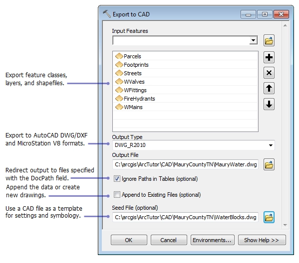
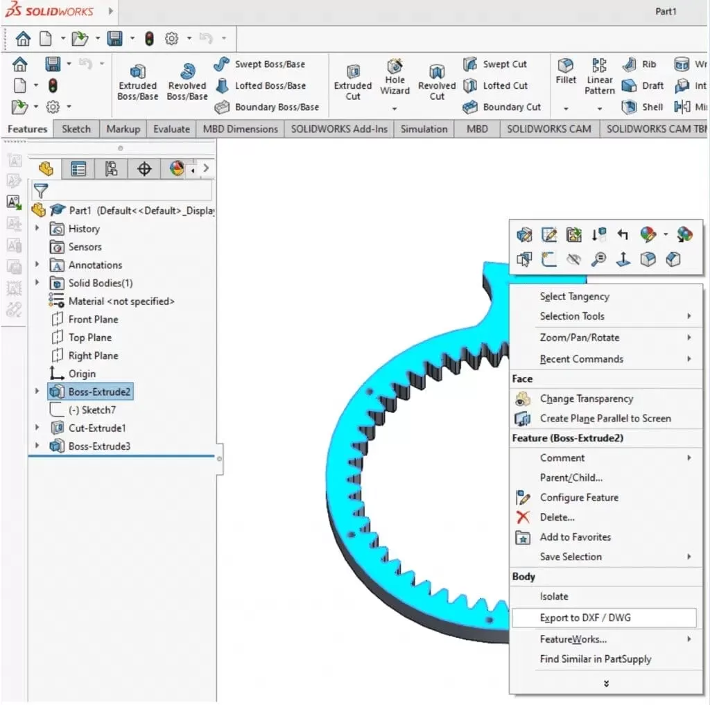
Go to File > Save As and choose DXF as the file type, or right-click the flat pattern in the feature tree and select Export to DXF/DWG.
Step 3 Configure Export Options
In the export dialog, make sure to:
- Uncheck any options related to kerf compensation, toolpath offsets, or automatic adjustments.
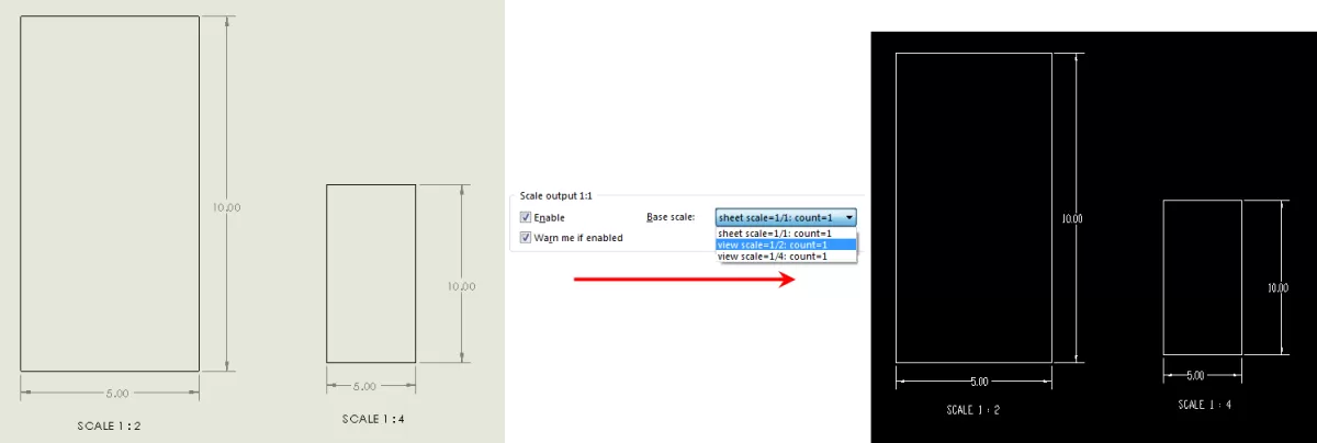
- Select Use sheet scale to keep the DXF at a 1:1 scale, matching your SolidWorks model exactly.
Step 4 Remove Annotations and Unnecessary Elements
Before saving, clear out all text, dimensions, and any extra objects like borders or frames. These can confuse CNC software and be mistaken as cut lines.
Step 5 Save and Verify the DXF File
Save your DXF and then open it in a reliable DXF viewer or CAD software. Double-check that:
- The geometry is clean with no unexpected gaps or overlapping lines.
- All lines are continuous and not split into separate entities unless needed.
- There are no offsets or scaling errors that would affect kerf-free cutting.
Following these steps ensures your exported DXF is ready for precision CNC machining with no kerf cuts.
Troubleshooting Common DXF Export Issues
Individual Line Entities
Sometimes, when you export a DXF from SolidWorks, laser cutters see each line as a separate piece. This can slow down the cutting and cause accuracy problems. To fix this, convert those separate lines into polylines or joined paths before export. Polylines keep your cuts smooth and continuous, which CNC machines prefer.
Scaling Errors
If your DXF file looks off in size when imported into CNC software, it’s usually a scale or unit mismatch. Always double-check your view and export settings in SolidWorks. Make sure your design is set to a 1:1 scale and that the units (inches or millimeters) match your CNC machine’s requirements. This prevents waste and keeps your cuts precise.
Kerf Compensation Applied Automatically
Some CNC programs automatically add kerf compensation after you export your DXF, even if your file is clean. To avoid confusion, verify with your CNC operator or software settings that no extra kerf offsets are applied post-export. This ensures the cutting path matches your original design, keeping your parts accurate and reducing the need for post-processing.
Optimizing DXF Files for HYCNC CNC Services
HYCNC’s CNC processing services work best when you provide clean, no kerf DXF files. A kerf-free file ensures the cutting path is exact, saving time and preventing mistakes during cutting. This means your parts come out with tight tolerances and minimal need for adjustments after cutting.
When uploading your DXF to HYCNC’s platform, keep these tips in mind for a smooth quoting and production process:
- Use a 1:1 scale file with the correct units (inches or millimeters) matching your order
- Keep your design layers organized—separate cut lines from etch or engraving lines to avoid confusion
- Remove extra notes or annotations that are not meant for cutting
- Double-check that all cut paths are closed contours to prevent errors
HYCNC offers precision cutting using advanced laser and waterjet technology. Their quality assurance process guarantees that your parts meet your specifications consistently. By sending clear, kerf-free DXF files, you help HYCNC deliver faster, more accurate results.
Best Practices for CNC Ready DXF Files
To get the best results when exporting your DXF files from SolidWorks for CNC cutting, follow these simple tips:
-
Use closed contours for cut paths
Make sure all your cut lines form closed loops. Open or broken lines can cause errors or incomplete cuts on CNC machines.
-
Test files with sample cuts or simulations
Before full production, run a simulation or a small sample cut. This helps catch any issues with the DXF geometry or scaling, saving time and material.
-
Communicate clearly with your CNC service provider
Every CNC shop has specific requirements, so talk directly with your provider like HYCNC. They can advise on file setups, kerf settings, and any adjustments needed to ensure smooth production.
Following these best practices will help you create clean, kerf-free DXF files ready for precision CNC machining without headaches.