Are you struggling to create text in SolidWorks for your CNC designs? Adding text to your 3D models can elevate your designs, ensuring clear part labeling, branding, or functional markings for manufacturing.
As a CNC machining expert, HYCNC understands the importance of mastering SolidWorks text tools to produce precise, professional parts. With years of industry experience, we’re sharing proven techniques to help you add text effortlessly.
In this guide, you’ll discover how to use Sketch Text, Wrap, and Extrude features to create text that’s ready for CNC machining. Whether you’re a beginner or a seasoned designer, these steps will streamline your workflow and enhance your designs.
Let’s get started!
Setting Up Your SolidWorks Environment Choosing the Right Plane or Surface Creating a Sketch for Text
Before you start creating text in SolidWorks, it’s important to set up your environment correctly. This ensures a smooth workflow and precise results. First, open your part or assembly and decide where you want the text to appear. SolidWorks text can be applied to flat or curved surfaces, so choosing the right plane or face is key.
-
Select the appropriate plane or surface:
- For flat text, pick a planar face or standard plane like Front, Top, or Right.
- For curved surfaces, consider using the Wrap feature later, but start by selecting the surface where your text will follow the contour.
-
Create a new sketch on the chosen plane or surface:
- Click “Sketch” and select the plane or face you identified.
- This sketch acts as the base for your text, so verify you are in the right orientation to avoid twisting or scaling issues later.
-
Prepare your sketch:
- If necessary, add reference lines or shapes to position your text accurately.
- Keep your sketch simple to prevent model complexity down the road.
By setting up SolidWorks this way and choosing the correct plane or surface, you’re ready to create precise, clean text sketches. This step saves time and avoids headaches when extruding, wrapping, or projecting text in your design. For more help on starting sketches, check out our guide on creating a 2D sketch in SolidWorks.
Step by Step Guide to Creating Text in SolidWorks
Creating text in SolidWorks is straightforward once you know the right tools to use. Here’s how to do it:
Using the Sketch Text Tool
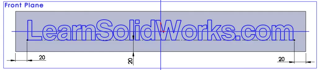
- Start a Sketch on the plane or surface where you want your text.
- Select the Text Tool from the Sketch toolbar.
- Click inside the sketch to open the text box.
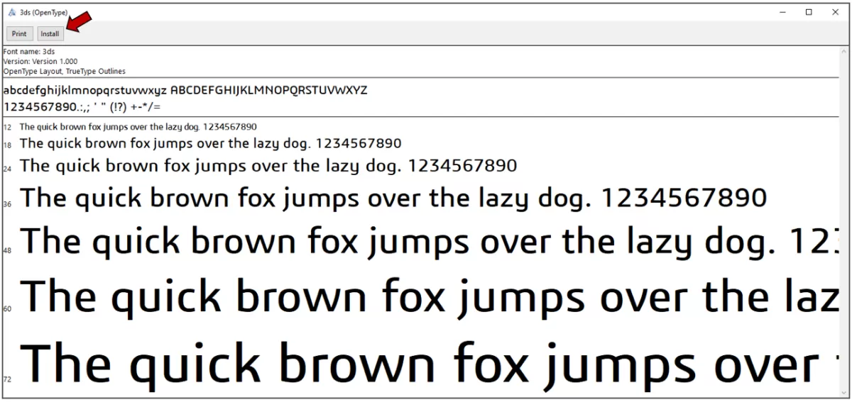
- Type your desired text and pick a font that works well for your project—keep CNC machining in mind.
- Position your text by dragging the box or entering exact coordinates.
Extruding Text for 3D Effects
- With your text still selected in the sketch, exit the sketch mode.
- Use the Extrude Boss/Base feature to give depth to your text.
- Adjust the extrusion height based on how raised or engraved you want the letters.
- This makes your text ready for embossing or engraving operations.
Wrapping Text on Non-Planar Surfaces
- If your text needs to go on curved or angled surfaces, use the Wrap Feature.
- After creating the text sketch, select Wrap under the Features tab.
- Choose between Emboss, Deboss, or Scribe options depending on how you want the text to interact with the surface.
- Select the curved face and apply the wrap to conform your text perfectly.
Projecting Text with Split Line
- For advanced designs, use the Split Line Tool to project text onto surfaces.
- Create a sketch with your text on a plane near the target surface.
- Use Split Line to project that sketch onto the surface, which helps separate the text area for further operations like coloring or cutting.
Following these steps makes it easier to create clear, precise text in SolidWorks suited for 3D printing, engraving, or CNC machining.
Best Practices for CNC-Compatible Text in SolidWorks

When creating text for CNC machining or laser cutting in SolidWorks, keeping a few key practices in mind will save time and ensure clean results.
Design Guidelines for CNC and Laser Cutting
- Choose simple, bold fonts: Stick to fonts without thin lines or intricate details. Fonts like Arial or Helvetica work best for CNC and laser cutting.
- Maintain clear spacing: Keep enough space between letters to avoid welding or cutting errors. At least 0.05 inches (1.27 mm) between characters is usually safe.
- Avoid very small text: Text below 0.1 inches (2.5 mm) can get lost or be hard to machine accurately.
Optimizing Text for Manufacturing
- Use sketch text instead of imported graphics: Sketch text adapts well during scaling and editing, making it easier to adjust in SolidWorks.
- Convert text to curves when needed: Use the “Convert Entities” feature to turn text edges into sketch lines. This gives CNC software clean paths to follow.
- Check extrusion depths carefully: For embossed or engraved text, keep extrusion shallow enough for precise cutting without damaging parts.
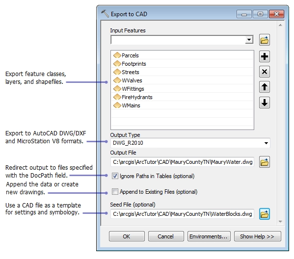
Exporting to DXF for CNC Machining
- Select the right face or plane: Export text sketches from a flat surface or plane for accurate 2D DXF files.
- Use “Save As” and choose DXF: In SolidWorks, export your sketch by going to File > Save As and selecting DXF or DWG format.
- Simplify your DXF file: Remove unnecessary geometry to reduce CNC programming complexity and avoid errors.
Following these solid practices helps your SolidWorks text come out sharp, precise, and ready for CNC or laser cutting jobs that meet professional standards.
Common Challenges and Solutions
Creating text in SolidWorks is straightforward, but you might run into a few common issues. Here’s how to tackle them:
Text Not Displaying in Drawings
- Check Sketch Visibility: Sometimes, the sketch containing the text might be hidden. Make sure the sketch is visible in the Feature Manager.
- Use the Right Font: Some fonts don’t show well or can cause issues in drawings. Stick to standard, CNC-friendly fonts.
- Update Drawing Views: If the text sketch is on a feature that’s suppressed or missing, the drawing won’t show it. Verify all related features are active.
Managing Model Complexity
- Keep Text Sketches Simple: Detailed fonts or complex outlines increase file size and slow down performance. Use simpler fonts or reduce the number of text bodies.
- Use Layers or Groups: Organize your text features separately to control visibility and edits easily without cluttering your model.
- Suppress Unused Text Features: If you have multiple text options, suppress the ones you’re not using to keep the model lean.
Troubleshooting CNC File Issues
- Check Export Settings: When exporting to DXF or other CNC formats, ensure the text is converted to curves or splines. Some CNC machines can’t read text as fonts.
- Avoid Overlapping Geometry: Overlaps can confuse CNC tools, causing errors during cutting or engraving. Use the Split Line feature carefully to keep outlines clean.
- Simplify Text Outlines for CNC: Complex outlines can cause toolpath errors. Use solid, closed profiles whenever possible.
By addressing these common challenges early, you’ll save time and avoid frustration when working on text designs meant for CNC machining or detailed drawings. For more on preparing text for CNC, check out our guide on exporting to DXF from SolidWorks.
How HYCNC Enhances Your SolidWorks Designs
When you create text in SolidWorks, getting precise, clean results during manufacturing is key. That’s where HYCNC steps in to enhance your designs with their expert CNC machining services.
Seamless Integration with SolidWorks
HYCNC works smoothly with your SolidWorks files, so you don’t have to worry about compatibility issues. Whether you’re exporting DXF files or sending complex 3D text features, their process is tailored to match SolidWorks workflows. This saves time and avoids common headaches when moving from design to production.
Precision CNC Machining for Text Features
HYCNC specializes in precision CNC machining that brings your embossed or engraved SolidWorks text to life. They understand the specific tolerances and detail levels needed for sharp, clean text on metal or plastic parts. Their expertise ensures your text features are crisp, whether flat, wrapped, or projected using SolidWorks tools like wrap, extrude, or split line.
In short, HYCNC makes sure your SolidWorks text isn’t just a design—it’s a perfectly crafted part ready for real-world use.
FAQs
How do I create text in SolidWorks?
Start by selecting the right plane or surface, then open a sketch and use the Sketch Text tool. You can type your text and adjust fonts before extruding or wrapping it.
Can I engrave or emboss text in SolidWorks?
Yes, you can extrude text inward for engraving or outward for embossing. Use the Extrude Cut feature for engraving or Boss-Extrude for embossing.
How do I wrap text on a curved surface?
Use the SolidWorks wrap feature to project your text onto non-flat surfaces. This makes your text follow the curve precisely.
What is the best font for CNC machining in SolidWorks?
Choose simple, clear fonts like Arial or Helvetica. Avoid complex or script fonts—they can cause issues during CNC or laser cutting.
How do I export text for CNC machining?
Once your text is created, save your sketch or face as a DXF file. SolidWorks DXF export is CNC-friendly and works well with most machining software.
Why isn’t my text showing in SolidWorks drawings?
Make sure your sketch with text is visible and not suppressed. Also, check if the drawing views include the text feature or the associated sketch.
How can I fix CNC file issues from SolidWorks text?
Simplify the text outlines by converting fonts to curves and removing unnecessary details. Use solid, closed profiles for reliable tool paths.
Does HYCNC support SolidWorks text features?
Yes, HYCNC provides precision CNC machining that perfectly matches your SolidWorks text designs, ensuring high-quality engrave and emboss results.
If you have other questions about SolidWorks text or CNC machining, feel free to reach out. We’re here to help you get the best from your designs.