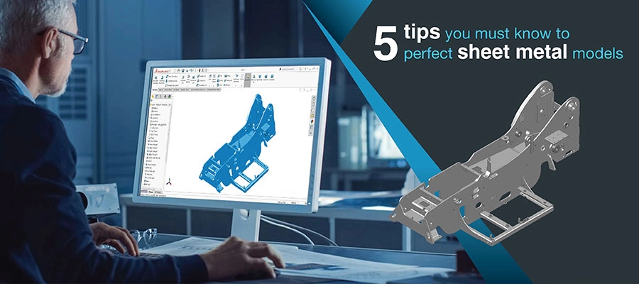
Are you ready to master sheet metal design using SolidWorks? Creating precise, manufacturable sheet metal parts can transform your projects, saving time and boosting efficiency. As a CNC processing expert, HYCNC knows that designing with SolidWorks is the key to seamless fabrication. In this guide, you’ll uncover practical steps, expert tips, and design for manufacturability strategies to elevate your workflow. Whether you’re a beginner or a seasoned designer, dive in to learn how to craft sheet metal parts that shine in production!
Understanding Sheet Metal Design in SolidWorks
What is Sheet Metal Design
Sheet metal design involves creating parts and components by shaping flat metal sheets through bending, cutting, and forming processes. These designs need to balance functionality, durability, and manufacturability. Unlike solid modeling, sheet metal design focuses on the thickness, bend allowances, and flat patterns crucial for fabrication.
Why Use SolidWorks for Sheet Metal
SolidWorks is one of the leading sheet metal CAD software programs, offering robust tools tailored for designing metal parts efficiently. It simplifies the process with features like the SolidWorks base flange tool, parametric modeling for easy updates, and the ability to quickly create flat patterns for CNC sheet metal fabrication. Designers can integrate complex geometries while maintaining manufacturability, saving countless hours from design through production.
Design for Manufacturability
Designing sheet metal parts isn’t just about the model—it’s about making sure your design can be built easily and cost-effectively. Design for manufacturability SolidWorks principles emphasize:
- Using standard bend radii and common metal thicknesses
- Avoiding overly tight bends that may cause material failure
- Planning for accessible cuts and holes to ease CNC machining
- Creating simple, flat patterns that reduce material waste
Applying these guidelines in SolidWorks helps streamline production and reduces back-and-forth with fabricators, ensuring your design turns into a real part without surprises.
Step-by-Step Guide to Designing Sheet Metal in SolidWorks
Getting started with sheet metal design in SolidWorks is straightforward once you know the basics. Here’s a simple breakdown:
Setting Up the Sheet Metal Environment
First, enable the Sheet Metal tab in SolidWorks if it’s not already visible. This gives you quick access to tools like Base Flange, Edge Flange, and Flat Pattern. Go to the Settings, customize the toolbar, and activate sheet metal features to get things rolling.
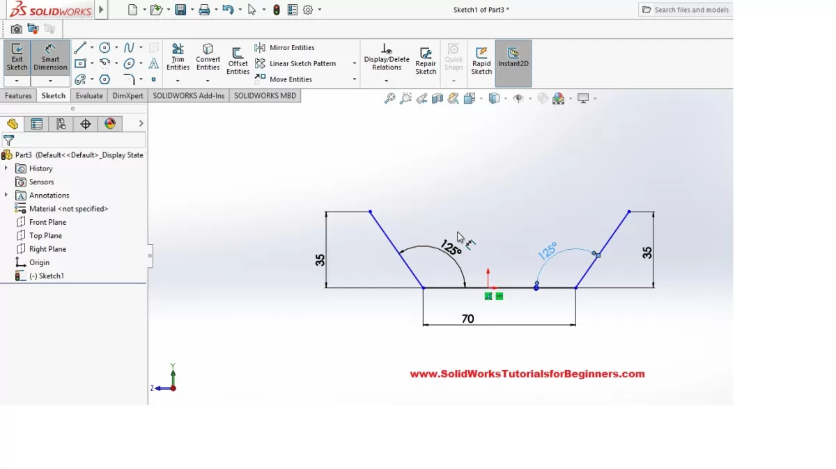
Creating a Base Flange
The Base Flange is your starting point—the flat piece of metal you’ll build off. Use the Base Flange tool to sketch your initial shape, setting the right thickness and material properties based on your project. This ensures the design will work well for CNC sheet metal fabrication later.
Adding Features
Once your base is set, add flanges, bends, hems, or jogs using the various sheet metal feature tools. These help shape the part for functional or assembly needs. Remember to watch for bend radius and relief options to avoid manufacturing issues.
Converting Solid Parts to Sheet Metal
If you started with a solid part, SolidWorks lets you convert it to sheet metal using the Convert to Sheet Metal tool. This helps when reusing existing designs but needs to meet sheet metal standards. You’ll define bend edges and thickness here.
Adding Cuts and Holes
Sheet metal parts often need holes or cutouts for screws, bolts, or weight reduction. Use Cut-Extrude and Hole Wizard features but keep in mind the manufacturability for CNC machining or stamping processes.
Generating Flat Patterns
Finally, create a flat pattern to see how the designed part will be cut and bent from a flat sheet. This is crucial for CNC services and fabricators to understand your part’s final shape. Use the Flat Pattern feature to export accurate layouts for production.
Following these steps will ensure your sheet metal design in SolidWorks is solid, manufacturable, and ready for production.
Best Practices for Efficient Sheet Metal Design
To get the most out of your SolidWorks sheet metal designs, following some best practices can save you time and headaches down the line.
Start Designs Centrally
Begin your sheet metal parts from a central, well-defined reference point. This keeps your design organized and makes updates easier, especially when dealing with complex assemblies.
Use Design Libraries
Leverage SolidWorks design libraries for common features like bends, tabs, and cutouts. It speeds up your workflow and keeps your parts consistent across projects.
Optimize Hardware Integration
Plan how your sheet metal will fit with other hardware early on. Factors like fasteners, brackets, and mounting points should be integrated within your SolidWorks parametric model to avoid rework.
Simulate Before Fabrication
Don’t skip simulation. Use SolidWorks’ bending and flattening simulation tools to test how your sheet metal will behave. This helps spot issues before CNC sheet metal fabrication, reducing costly mistakes.
Collaborate with Fabricators Early
Get in touch with your fabricators early in the design process. Their feedback on manufacturability often highlights practical changes to improve design for manufacturability in SolidWorks, saving time and money during production.
Common Challenges and Solutions in SolidWorks Sheet Metal Design
Designing sheet metal parts in SolidWorks isn’t always straightforward. You’ll likely run into some common challenges, but there are solid ways to handle them.
Complex Geometries
Sheet metal parts often have tight bends, intricate curves, or multiple flanges. These can be tough to model and might cause errors when trying to create flat patterns.
Solution: Use SolidWorks’ bend tools carefully and keep your bends within manufacturable limits. The base flange tool combined with precise bend radius settings helps avoid over-complicated shapes. Breaking down the part into simpler features also works well.
Manufacturability Issues
What looks good in SolidWorks might not always be easy to build, especially for CNC sheet metal fabrication. Some designs might require excessive bending or cutting, pushing machine limits.
Solution: Design for manufacturability by consulting with fabricators early. Use SolidWorks’ DFM (Design for Manufacturability) tools or add-ins to spot problem areas before sending files out. Always check the flat pattern for potential issues.
Time-Intensive Processes
Creating detailed sheet metal parts, especially converting complex solid parts into sheet metal, can take a lot of time. Tight deadlines often add pressure.
Solution: Streamline your workflow by using design libraries and reusable features. Automate repetitive tasks with SolidWorks macros or add-ins like SheetMetalWorks. Also, start with parametric modeling so changes are quicker to implement.
By addressing these challenges head-on, you’ll save time and ensure your sheet metal designs work smoothly from SolidWorks to the shop floor.
How HYCNC Enhances Your SolidWorks Designs
When you’re designing sheet metal parts in SolidWorks, getting from the drawing board to production can be tricky. That’s where HYCNC steps in to make the process smoother and more efficient.
From Design to Production
HYCNC specializes in CNC sheet metal fabrication, meaning they take your SolidWorks designs and turn them into precise, ready-to-use parts. They understand SolidWorks sheet metal tutorials and best practices, so your files are handled with care throughout the manufacturing process. This ensures you get accurate bends, cuts, and holes exactly as designed.
DFM Feedback
One of the biggest advantages of working with HYCNC is their design for manufacturability (DFM) feedback. They review your SolidWorks base flange and flat pattern files to spot issues that could cause problems in production. This early feedback helps you avoid costly revisions and delays, making sure your part designs are ready to manufacture right from the start.
File Compatibility
HYCNC supports a wide range of file formats from SolidWorks, including native part files and exported CAD tutorials-compatible formats. This compatibility means there’s no guesswork or file corruption during transfer. Your parametric modeling data stays intact, preserving the integrity of your design for quick turnaround times.
Case Study
For example, a local U.S. manufacturer recently partnered with HYCNC to produce complex sheet metal parts designed in SolidWorks. Thanks to HYCNC’s expertise and DFM insights, the project hit every milestone on time and stayed within budget. The seamless integration between SolidWorks designs and CNC machining services showed how crucial a reliable partner is in sheet metal fabrication.
Working with HYCNC means you get more than just a service — you get a collaborative partner that helps your SolidWorks sheet metal designs move from concept to reality with ease.
Advanced Tools and Add-Ins for SolidWorks Sheet Metal
When you’re working with sheet metal designs in SolidWorks, sometimes the default tools aren’t enough, especially for complex projects or when you want to speed up your workflow. That’s where advanced add-ins come in handy.
SheetMetalWorks Add-In
SheetMetalWorks is a popular add-in that expands SolidWorks’ native sheet metal capabilities. It offers enhanced features like quick bend radii adjustment and improved flat pattern accuracy. This tool is great if your projects require precise control over metal bends and detailed manufacturing specs.
3D SheetMetal Creator
The 3D SheetMetal Creator add-in is perfect when you want to model complex sheet metal parts in 3D with more freedom. It lets you create bends, cuts, and forms directly on 3D surfaces, which is a game changer for complicated geometries or custom designs.
When to Use Add-Ins
- Complex Bending Requirements: When standard bending tools don’t cut it, add-ins provide the extra flexibility you need.
- Speeding Up Repetitive Tasks: If you find yourself doing the same operations over and over, add-ins can automate or simplify these steps.
- Improving Flat Pattern Accuracy: Some add-ins help generate more reliable flat patterns for CNC sheet metal fabrication.
- Handling Detailed Custom Designs: When your sheet metal parts get intricate, add-ins can offer enhanced tools tailored for those needs.
Using these advanced tools can help you streamline your sheet metal design process in SolidWorks and deliver better results for fabrication. For more on improving your sheet metal workflow, check out resources on using SolidWorks convert to sheet metal tool and explore efficient metal bending services.