Why 2D Sketching in SolidWorks Matters
2D sketching is the foundation of every design in SolidWorks, especially when preparing parts for CNC machining. A precise 2D sketch allows you to create accurate profiles that machines follow, making it essential for CNC design. SolidWorks lets you build these sketches with exact dimensions and relationships, ensuring parts come out just as intended.
One of the biggest advantages of using SolidWorks 2D sketches is parametric modeling. This means you can easily edit your design later by changing dimensions or constraints without redrawing from scratch. Parametric sketches save you time and reduce errors, making revisions smooth and efficient.
Whether you’re designing simple parts or complex components, mastering 2D sketching is key to producing high-quality CNC-ready models. It helps bridge the gap between your idea and the final machined product with precision every step of the way.
Getting Started with SolidWorks

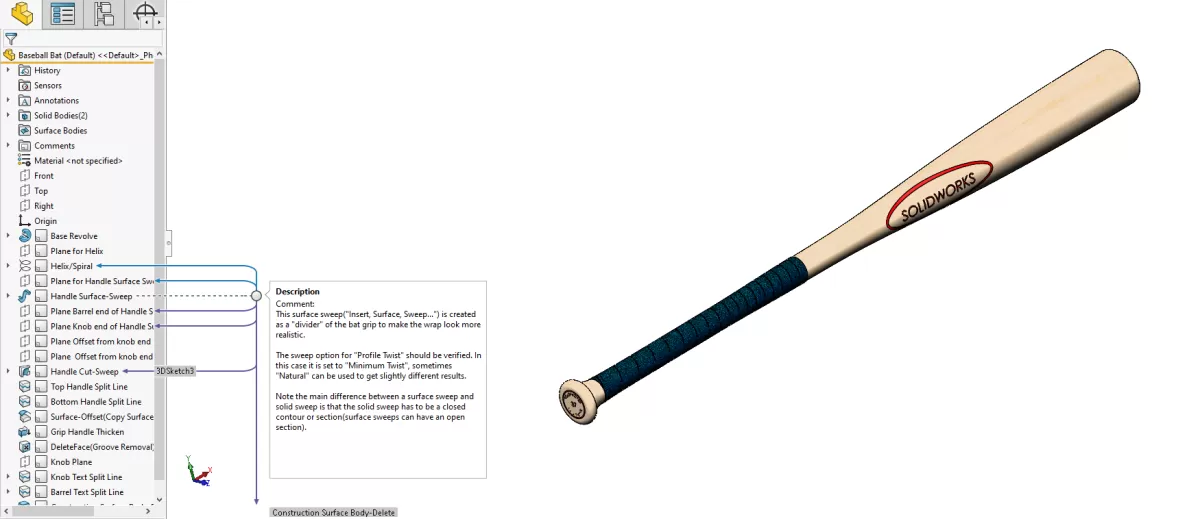
Jumping into SolidWorks to create your first 2D sketch is pretty straightforward. Start by opening a new part file. You’ll be prompted to select a plane—usually the Front, Top, or Right plane. Picking the right plane sets the stage for your design, so think about how you want your sketch oriented.
Once you have your plane, the SolidWorks interface comes into view. It might feel busy at first, but key areas to focus on are the Feature Manager on the left, the Command Manager at the top, and the graphics area where you’ll draw. Keep an eye on the Heads-Up Toolbar too; it’s handy for quick tools.
A few quick tips to get comfortable with viewing your sketch:
- Zoom in and out with your mouse scroll wheel for precision.
- Pan by holding the middle mouse button and moving the mouse. This helps you navigate around your sketch without losing focus.
- Use the View Orientation box (spacebar shortcut) to switch between standard views quickly.
Getting the hang of these basics makes working on your SolidWorks 2D sketch easier, especially as your designs get more detailed.
Step-by-Step Guide to Creating a 2D Sketch
Starting a 2D sketch in SolidWorks is straightforward once you get the hang of it. Here’s a simple walkthrough:
- Start a new sketch: Open your part file, then pick a plane to sketch on—usually Front, Top, or Right. Just click the plane and hit “Sketch” from the toolbar.
- Use sketch tools to draw shapes: SolidWorks offers basic tools like line, rectangle, circle, and arc. Grab the tool, click to place points, and create your shapes. Don’t worry about perfect size yet.
- Apply constraints and relations: To keep your sketch organized, add constraints like horizontal, vertical, or equal length. Relations help keep parts aligned and behave predictably when edited.
- Use the Smart Dimension tool: This tool is key. Click on lines or points to set exact lengths, angles, or distances. It defines the size of your sketch elements so your design is precise.
- Check for a fully defined sketch: Look for the color of your sketch lines. Blue means underdefined, black means fully defined. A fully defined sketch won’t move accidentally during modeling.
- Save and exit the sketch: When you’re done, click “Exit Sketch” or just close the sketch mode. Remember to save your part file regularly to avoid losing progress.
Following these steps helps you create clean, precise 2D sketches perfect for further CAD work or CNC machining preparation.
Best Practices for 2D Sketching in SolidWorks
To get the most out of your SolidWorks 2D sketching, keeping your sketches simple and clean is key. Avoid clutter by focusing only on the shapes and features you need. Use construction lines and centerlines to help organize your sketch without adding unnecessary geometry that might complicate later steps.
Always apply constraints before adding dimensions. This helps lock your sketch’s shape and relationships first, making sure your design behaves predictably when edited. Don’t forget to regularly check that your sketch scale matches CNC requirements—this stops errors when moving from design to machining.
Stay organized by naming your sketches clearly. This is especially useful if you’re managing multiple sketches in one project or handing files off to others.
If you’re working with HYCNC or any CNC service, follow their specific file requirements for sketch exports. Making sure your 2D sketch meets HYCNC’s standards can save time and avoid costly rework in CNC machining. Properly preparing your sketches by following these best practices lets you take full advantage of SolidWorks for smooth CNC production.
Common Mistakes to Avoid When Sketching
When creating 2D sketches in SolidWorks, it’s easy to run into common pitfalls that can slow down your workflow or cause issues with CNC machining. Here are some mistakes to watch out for:
-
Overcomplicating sketches
Keep your sketches simple. Adding too many details or unnecessary lines makes editing harder and can confuse CNC software. Focus on the key shapes and features you need.
-
Leaving sketches underdefined
Always fully define your sketches by applying the right constraints and dimensions. Underdefined sketches can cause unexpected changes when you modify the design later.
-
Missing constraints
Don’t skip constraints like horizontal, vertical, or equal length. Missing constraints lead to unstable sketches that can’t be reliably used for CNC machining or 3D modeling.
-
Ignoring CNC-compatible file standards
Make sure your sketch meets CNC requirements. Use the right scale, avoid open profiles unless intentional, and export in compatible formats like DXF. This ensures smooth processing when sending to services like HYCNC.
Following these tips keeps your SolidWorks 2D sketches clean, reliable, and ready for CNC machining without extra headaches.
From 2D Sketch to CNC Machining with HYCNC
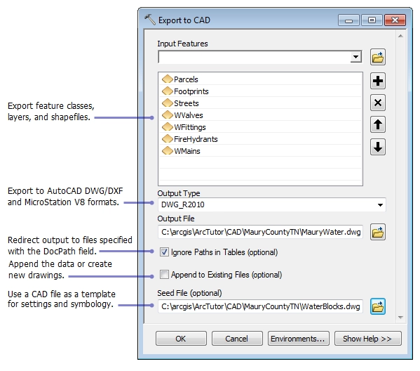
Once your 2D sketch is ready, exporting it as a DXF file is the next step for CNC machining. SolidWorks makes this easy—just save your fully defined sketch as a DXF, which is the preferred format for most CNC machines.
Before sending your file to HYCNC, make sure you follow their pre-flight checklist:
- Verify your sketch is fully defined with no open contours
- Use proper scale and units compatible with machining
- Clean up any extra lines or construction geometry
- Name your file clearly for easy identification
HYCNC then takes your DXF and converts the 2D sketch into precise CNC toolpaths. Their service transforms your design into real parts with accuracy and speed, ensuring your project runs smoothly and meets US manufacturing standards.
Ready to get started? Upload your SolidWorks 2D sketches to HYCNC today and bring your designs to life with professional CNC machining.
FAQs About 2D Sketching in SolidWorks
What is a 2D sketch in SolidWorks?
A 2D sketch is the foundation for any part you create in SolidWorks. It’s basically a flat drawing made on a plane using lines, circles, arcs, and other shapes. This sketch shapes how your 3D model will form, so getting it right is key.
How do I check if my sketch is fully defined?
SolidWorks shows the sketch color to help here. Blue lines mean underdefined—your sketch still needs constraints or dimensions. Black lines mean fully defined—the shapes have fixed sizes and positions. You can also look at the status bar at the bottom to confirm if the sketch is fully defined.
Can 2D sketches be used for CNC machining?
Yes! 2D sketches are common starting points for CNC jobs. You export your sketch as a DXF file that CNC machines can read to cut or engrave parts. Make sure your sketch is clean, fully defined, and follows CNC file standards to avoid issues.
How do I export sketches for CNC?
Once your sketch is ready, go to the File menu, choose Save As, and pick the DXF format. This format works great for most CNC services, including HYCNC. Before exporting, double-check that your layers and lines meet CNC requirements.
What are the best tools for beginners in SolidWorks sketching?
Start with basic tools like:
- Line, Circle, Rectangle for shapes
- Smart Dimension to set exact sizes
- Relations and Constraints to lock shapes in place
Learning these tools helps you build clean, easy-to-edit sketches fast.
For more info on exporting parts, check out this guide on how to export a STEP file from SolidWorks. It’s another useful skill once your 2D sketch turns into 3D.